Nibbus Maximus: 3d Photo Journal

4 - 2

Reposting from the halcyon days of 2011.

The family and I went up to Skinner Hall this afternoon where our friends at Gage School of Fine Arts were hosting the pen and ink artist, Jim Woodring.  Woodring was giving the first public showing of his giant pen Nibbus Maximus, and was allowing members of the public to use the pen to complete a giant drawing.  The following pictures are in 19th century stereocard format, which somehow seemed appropriately surreal.

(The pictures can be viewed in 3D using “relaxed eye stereo” viewing. See How to view 3D digital photos without breaking the bank for more info on 3D viewing).

1 - 2

Lovely car on the way in.


6 - 2

Poster in the rain


2 -2

First glimpse of the pen


3 - 2

Woodring and Nibbus Maximus

7 - 2

The pen is passed on

8 - 2


9 - 2

The giant nib in action

10 -2


11-2

5 - -2

Pen and ink was available for all

12 -2


14-2

Let us know what you think in the comments below!

Using the Arduino for electronic music #3

Testing the analog output resolution of the Euroduino:

Note: Audio samples are not included yet, and there are more tests to be done on the sample rate section.

The previous articles in this series are:

So far, we have dealt with the subject in the abstract, using best case scenarios and working from specification sheets.  Reality is, as always much more messy.  To start with, lets look at the most problematic part of the platform, the analog outputs of the Arduino in it’s default state using the Euroduino module as a testing ground.

It is simple enough to write an Arduino program to output very specific values, and to chart those values to see if they are being translated as we expect them to be.

Bit depth

Ideally, bit depth should be at least 12 bits.  The PWM output of the Arduino falls considerably short of that, with only 8 bits of resolution.  Lets see how that 8 bits performs.

updated bit value to voltage

This chart compares the values used in analogWrite() commands with the specific voltages output on the cv out 1 port.  The code to do this is simple, and I stepped through the values in units of 12 so that I could get good voltage readings and not spend all day comparing values in the serial window to my voltmeter.

What it shows is that the Euroduino/Arduino has good linearity, so we can make some observations that will make programming easier:

  • Output changes linearly compared to input.
  • There is a inverse relationship between the written bit value and the voltage.
  • The circuitry of the Euroduino over and undershoots the 0 to 5 volt range that is common for modular control signals.  0 volts starts at around 246, and 5 volts ends at 12.  This means that (for the tested device at least), the range of 0 to 5 volts falls into the output range of 12 to 246, giving a 5 volt range (and therefore 5 octaves) spread over 234 values.
  • An octave then is represented by 46.8 steps (234/5=46.8).  Even though the analogWrite() command can only take integer values, it is valuable to track these values as floating point values so that errors do not accumulate.
  • A semitone is represented by 3.9 steps.  (234/(12*5)=3.9).

Hearing is believing

It is simple to write a program to play a slow descending glissando in order to see how smoothly the device can perform.  We already know from part two of this series that the output is not expected to be smooth, rather that there will be some noticeable stair-stepping, and that note values are not going to be precisely in tune.  A simple program can tell us if this is actually the case.

All the code in this post will use some common definitions, taken from Tim Ressel’s sample program that accompanies the Euroduino.

// These constants won't change.  They're used to give names
// to the pins used:
const int analogIn1Pin = A0;  // Analog Input 1
const int analogIn2Pin = A1; // Analog Input 2
const int analogPot1Pin = A2;  // Pot 1
const int analogPot2Pin = A3; // Pot 2
const int analogOut1Pin = 5;  // Analog Output 1
const int analogOut2Pin = 6; // Analog Output 2
const int DigitalIn1Pin = 8;  // Digital Input 1
const int DigitalIn2Pin = 9;  // Digital Input 2
const int DigitalOut1Pin = 3;  // Digital Output 1
const int DigitalOut2Pin = 4;  // Digital Output 2
const int Switch1Up = A4;  // Switch 1 Up
const int Switch1Dwn = A5;  // Switch 1 Dwn
const int Switch2Up = 7;  // Switch 2 Up
const int Switch2Dwn = 2;  // Switch 2 Dwn
void setup() 
{
    /* Set up I/O pins */
    pinMode(DigitalIn1Pin, INPUT);
    pinMode(DigitalIn2Pin, INPUT);
    pinMode(DigitalOut1Pin, OUTPUT); 
    pinMode(DigitalOut2Pin, OUTPUT); 
    pinMode(Switch1Up, INPUT_PULLUP);
    pinMode(Switch1Dwn, INPUT_PULLUP);
    pinMode(Switch2Up, INPUT_PULLUP);
    pinMode(Switch2Dwn, INPUT_PULLUP);
    Serial.begin(9600);  // if needed by Serial.print() etc.
}

To output a descending glissando, add the following code:

unsigned char Out1 = 12;
void loop ()
{
    analogWrite(analogOut1Pin, Out1);
    Out1++;
    if (Out1 > 246) Out1 = 12;
    delay(500);
}

Here is a sound file created by routing the CV 1 output of the Eurduino (running this program) to a Tiptop Z3000 oscillator.

Stair-stepping is obvious – the pitch descends in a series of discrete steps, not smoothly.  Looking at the code, it is clear that this is pretty much the maximum resolution achievable without hacks.

Sampling rate

PWM on the Euroduino runs at a particular frequency determined by the system clock speed.  For timer 0, which is what the Euroduino exposes, the PWM frequency is determined by the system clock divided by the prescaler, and then by the 256 steps used by the counter.  16 Mhz / 64 / 256 = 976.56 Hz, roughly a sample rate of 1k.  It is possible to increase this rate, but not without causing other Arduino functions to malfunction.

You can call analogWrite() much faster than 1k of course, but it is wasted effort and will likely cause unpredictable results since the compare value would be changing unpredictably.

Just for fun you can test this and remove the delays and print statements from the last program to see how fast a stock Arduino program can call analogWrite(). (print always adds a lot of overhead that would otherwise mess up calculations).

unsigned char Out1 = 12;
unsigned long startMicros;
unsigned long stopMicros;
unsigned char Out1 = 12;
unsigned long startMicros;
unsigned long stopMicros;
void loop ()
{
    //start test now
    startMicros = micros();
    for (unsigned int x = 0; x < 1000;x++)
    {
        // write a descending sawtooth wave to the output
        analogWrite(analogOut1Pin, Out1);
        Out1++;
        if (Out1 > 246)Out1 = 12;
    }
    // print takes place outside of the test loop
    stopMicros = micros();
    unsigned long resultMicros = stopMicros - startMicros;
    float samplesPerSecond = (float)1000000000 / resultMicros ;
    Serial.print ("Samples per second = ");
    Serial.println (samplesPerSecond);
    delay(5000);  //long enough to read the output
    //repeat and see if there is variance in the output
}

Here is the output of the test:

samples per second

(why the Arduino does not allow copy is beyond me)

This tells us that we can write the output roughly 118 times faster than the output is updated.  Adding the second output port:

analogWrite(analogOut2Pin, Out1);

brings us down to around 62 times faster.

two outputs

In either case, this sounds plenty strange.

It would be nice to know when it is time for a new sample to be written, and there are interrupts intended to allow this sort of thing.

There is an interrupt that tells us when the counter has overflowed and reset, which would be perfect, but that is already taken by the Arduino library.

The next best thing is to use an interrupt that triggers when the counter reaches a certain number.  Adafruit, one of the primary distributors for all things Arduino, has a good info page at: https://learn.adafruit.com/multi-tasking-the-arduino-part-2/timers which gives detail on strategies for using timer0 interrupts within the Arduino environment.

The following code sets it to trigger at the maximum value of the counter, which is about as close to the overflow interrupt as we can get.

This code is added to the setup loop:

OCR0A = 0xFF;
TIMSK0 |= _BV(OCIE0A);

And here is the code for the interrupt body itself.

unsigned int count = 0;
bool state = 0;
// Interrupt is called once a millisecond, every time the PWM counter maxes out.
SIGNAL(TIMER0_COMPA_vect) 
{
    count++;
    if (count > 1000)
    {
       count = 0;
       if (state == 0) state = 1;
       else state = 0;
       digitalWrite(ledPin, state);
    }
}

Add this code to an Arduino program, and the interrupt will be called one thousand times a second.  In this example, it simply flashes the led on pin 13 on and off, telling us that it is working.

Next, we should update our descending tone code to call analogWrite() only when it is safe.  I also added a delay of half a second so that the steps of the glissando would be more apparent.

unsigned int count = 0;
unsigned char outputValue = 12;
// Interrupt is called once a millisecond, every time the PWM counter maxes out.
SIGNAL(TIMER0_COMPA_vect) 
{
    count++;
    if (count > 500) //change every half second
    {
        count = 0;
        outputValue ++;
        if (outputValue > 246) outputValue = 12;
    }
    analogWrite (analogOut1Pin,outputValue);
}
void loop ()
{
     // all other code goes here and will not interfere with the updating of the output values.
}

Note that there is no code left in loop – all management of the output buffer is done in the interrupt!

Hacks to improve output bit depth

It may be possible to dither the output to add a couple of bits resolution.  Dithering is, roughly speaking when you alternate two adjacent values in an attempt to simulate a third value that lies between them.  What this would take would be to change the value used in analogWrite() every time a sample is output to add either a 1 or a 0 to the output depending on output value.  This would allow an extra bit of precision at the cost of some ripple in the output, and some complexity to the program.  With any luck, the filter capacitors on the output of the Euroduino (that are needed for PWM anyway) will help remove most of this additional ripple.

Here’s  a short experiment to see if dithering makes any difference, and if so, if it has any artifacts that are unwanted:

unsigned int outputValueA = 12;
unsigned int outputValueB = 12;

bool count = 0;
// Interrupt is called once a millisecond, every time the PWM counter maxes out.
SIGNAL(TIMER0_COMPA_vect) 
{
   // toggle between dithered values
   count = !count; 
   if (count) analogWrite (analogOut1Pin,outputValueA);
   else analogWrite (analogOut1Pin,outputValueB);
}

unsigned int increment = 24;
void loop ()
{
   // without dithering
   Serial.println ("without dithering");
   for (increment = 24; increment < 300; increment ++)
   {
     delay (250); // change values every 1/2 second.
     if(increment % 2) // if increment is odd
   {
     // don't dither output
     outputValueA = increment/2;
     outputValueA = (increment/2);
     digitalWrite (ledPin, 0);
   }
   else //increment is even
   {
     // don't dither output
     outputValueA = increment/2;
     outputValueA = increment/2;
     digitalWrite (ledPin, 1);
   } 
 }
 
 // with dithering

 Serial.println ("with dithering");
 for (increment = 24; increment < 300; increment ++)
 {
   delay (250); // change values every 1/2 second.
   if(increment % 2) // if increment is odd
   {
     // dither output
     outputValueA = increment/2;
     outputValueA = (increment/2)+1;
     digitalWrite (ledPin, 0);
   }
   else //increment is even
   {
     // don't dither output
     outputValueA = increment/2;
     outputValueA = increment/2;
     digitalWrite (ledPin, 1);
   } 
 }
}

As it turns out, that works well, even if it does cut the actual update rate by 50 percent.

Dealing with PWM and dithering noise

When I attached an oscilloscope to the output channels of the Euroduino, I expected to see some noise from the dithering code above, but expected the output to otherwise be fairly clean.  I was surprised to see how much ripple was making it out of the PWM, and how much effect this had on the quality of the audio from the voltage controlled oscillator (VCO). I was also surprised to see what little effect the dithering was having on the output.

I consulted the online RC Low-pass Filter Design Tool to get some values for an additional low pass filter, this time set to a conservative 1K (remember that 1 K is about the lowest we can safely go when dealing with control voltages).

CRLowPass

The returned values were:

1uf for the capacitor

160 ohms for the resistor

For 2k, the program suggests 820 ohms and a 0.1uf capacitor.  For 500 hz cutoff, the values are 1uf and 330 ohms.

Implementing the 1k circuit on a breadboard and adding it to the outputs of the Eruoduino, the ripple goes away.  In addition the audio from the VCO sounds cleaner – previously there were what sounded like faint difference tones in addition to the actual sine wave of the audio – perhaps an unintentional bit of FM synthesis.  These have disappeared completely.

Modding the circuit is cheating, I suppose, but it, along with the dithering of the output has produced a much more musical result.  I suppose that if you have need for DC control voltage response above 500k, this might not be for you.  And if you do, let me know – I’m really curious to know what it might be and add it into my considerations.


Using the Arduino for electronic music #2

How much of what we want can the Arduino do?

12493708_10207025983942846_6998465687837053403_o

This article is a continuation of Using the Arduino for electronic music #1, and picks up where that post left off.

By now we have discussed:

It’s now time to dig into the abilities of the Arduino, particularly it’s ability to handle analog to digital conversion, and digital to analog conversion.  Having done that, we can compare expected performance to the specifications listed in: The digital representation of modular synthesizer signals, and we can determine what an Arduino (and by extension the Euroduino eurorack synth module) is good for in electronic music.

What features are exposed by the Arduino, and the Euroduino?  Are there additional features in the native hardware of the  ATmega328P chip that are not supported in Arduino software or hardware?  Take a look at the following sections.

  • Analog input
  • Analog output
  • Digital input
  • Digital output

Analog input

Arduino

6 channels of 10 bit ADC

ArdGen_UNO

Your program can access the Arduino’s ADC converters using the Arduino AnalogRead command. The documentation for this command tells us that it takes about 100 microseconds (0.0001 s) to read one port.  this means that no more than 10,000 conversions can be made per second.  If all 6 ports are in use, then the sample rate for all channels can’t exceed 1,666.

The analog inputs on the Arduino connect to actual analog to digital converters (ADC) which convert analog signals to 10 bit binary numbers. 10 bits represents 1024 steps, a range of 0 to 1023.

Euroduino

4 channels of 10 bit ADCDSC07926

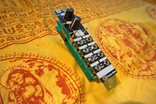
The Euroduino has the same capabilities as the Arduino Pro Mini that it is based on, but only 4 of the 6 ADC channels are exposed on the front panel by the 2 knobs and the 2 control voltage inputs.  If all 4 of these are in use, that means the Euroduino can sample all 4 at 10 bits 2,500 times a second.

To put this in perspective, a digital audio signal from a CD player samples a 16 bit value at 44K, or 44000 times a second.

It is clear that the Euroduino is not going to be processing audio, at least what we usually think of as audio – and that’s OK.  Knobs don’t need that kind of speed (how fast can you turn a knob?), and a control voltage signal (which is what these ports are designed to read) requires much less resolution.

ATmega328P

6 channels of 10 bit ADC

ATMEGA328P-AU TQFP32 Atmel
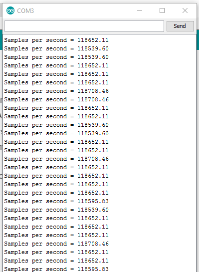
The microprocessor in its native state (without the overhead of the Arduino library) still has 6 ADCs. These produce 10 bit sample as often as 15,000 times a second according to the data sheet.   If all channels are being run, that would mean you can expect to get  2500 samples a second across all inputs.

The Arduino has an external clock, which overclocks the chip at 16 mhz.  When used without external clock support, the device runs at half that speed, 8 mhz.

Analog input: Will it perform?

It makes sense that the best performance will be seen from the bare chip, which runs without the overhead of the simplified Arduino environment.  Still, without going outside of the stock configuration, there is not much difference between the two.

For quality audio? No.

It is clear that the Arduino and Euroduino are not going to be processing audio, at least at the sort of rates we usually associate with audio – and that’s OK.  The Euroduino does not claim to process audio (all the analog ports are marked for control voltage), and the knobs do not need a very fast sample rate at all to perform well.

For quality LFO signals? Mixed.

Control voltage signals require much less resolution, although that resolution varies according to the signal type (The digital representation of modular synthesizer signals).  All types will perform well at the stock sample rates, both within the Arduino environment, and outside of it.  Where they vary is bit depth.  A LFO signal is still an audio level signal, and as such needs between 12 and 16 bits of depth.  Since the Arduino (etc.) only provide 10 bits ADC at best, the quality is still going to be sub-par.

For envelope and volume modulation CV?  Excellent.

For the DC, 0 to 5 volt signals that are used for volume and filter envelopes, 10 bits should be more than enough, and available sample rates sample rate is well below the available limit.

For 1 volt per octave control signals? Almost good enough.

Although the stock sample rate is probably in the range of just fine to great, the bit depth is barely adequate.  Ideally the bit depth would be at least 12 bits in order to represent tuning and smooth glissandos in higher registers, and we only have 10 at most.  1024 steps will not produce a smooth transition between values when mapped to high frequencies there will be some stair stepping (zipper noise) – just the sort of noticeable, annoying artifact that has always given digital electronic music a bad name.  It’s a pity, because that is the sort of thing I would really like to be able to process.

Conclusion

Decidedly a mixed bag. Although there are some digital modules out there that perform as well (or poorly) as the Arduino does, do we really want to be like them?  It is probably best if you limit your ideas to implementations that process:

  • Monopolar control voltages like envelopes and monopolar LFOs.
  • Pitch control voltages that use specific values (perhaps a sequencer that generates specific intervals with no vibrato, portemento or smooth slides between notes.)  There is no reason that you can’t support interesting tunings, as long as you accept that you won’t be exactly on target.  Analog VCOs are notorious for their inability to accuratly deliver precise tunings, so that may not be such a bad thing.

Work arounds

Open Music Labs has a great add on board for the Arduino the Audio Codec Shield which adds high quality CD level ADCs and DACs to your Arduino.

Advanced users might implement 12c or SPI ADCs that would support higher quality outputs if they are designing their own circuit and not using the Euroduino.

audiocodec_blue-1

Open Music Labs (which makes a great, high quality Arduino shield that supports high quality ADC and DAC) has a great article on using the ATmega line for audio, with some really interesting and borderline scary experiments pushing the chip to its limits  ATmega ADC.  Some of these give adequate performance with a sample rate as high as 32,000 samples per second. Still with 10 bit (or a little less) bit depth.


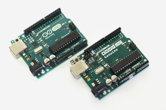
This works with stock Arduinos, as well as higher performance boards like the Leaflabs Maple (sadly discontinued).

This shield supports a sampling rate of up to 88K at a bit depth of 24  bits.  Since the Arduino can’t handle this range, the fact that it runs as slowly as 2K is much more interesting for our purposes.  There are two channels in and out of the board, and the board is DC coupled, which means it can output slowly changing DC control voltages without issue.  This board, an Arduino Uno, and your own signal conditioning circuitry would make a really good synth module.  It will not (of course) work with the Euroduino.

Open Music Labs has a great article on pushing chips in the ATmega family (like the arduino) to their limits for audio:  ATmega ADC.

Analog Output

Arduino

6 channels of 8 bit PWM

ArdGen_UNOOutput is where the rubber meets the road.  Sadly, this is the Arduino’s Achilles heel.  Where the ATmega 328 has actual ADCs, even if they are limited to 10 bits, the chip uses re-purposed digital outputs for PWM “analog” output.  This produces at best, a dirty 8 bit output when using the Arduino library.  It turns out that two of the PWM outs Your program writes to the Arduino’s PWM outputs using the Arduino analogWrite command.

The Arduino site has a quick introduction to PWM if you need to catch up.

The Arduino library also has an analogWriteResolution command, but it is intended to support the Arduino Due and the Zero.  These boards support up to 12 bit PWM, and 1 to 2 channel DACs.  Sadly, this does not affect the chips we are working with.

Sample rate:

The default sample rate of arduino PWM output is 488 times a second, which falls into the “barely adequate” range. There are hacks to improve this – See the ATmega 328 section for options outside of the Arduino library.

16 bits?

Timer 1 supports 16 bit PWM, which has more than enough accuracy – but it is not supported by the Arduino libraries.  See the ATmega 328 section for other details.

Euroduino

2 channels of 8 bit PWM

DSC07927The Euroduino has all the flaws from the Arduino section listed above, and in addition does not expose the PWM channels that can be associated with 16 bit PWM (as far as I can see, anyway).  Too bad about that.  Might just be worth modifying the device.

Here’s my reasoning to make that claim – love to hear that I was wrong:

Looking at the schematics for the Euroduino, the Arduino Pro Mini, and the datasheet for the ATmega328, this is what I see.

Front Panel CVOUT <-pin 4 SV1 <-SV3 pin <- conditioning circuit <- PWM1/1.2C <- PWM1/2.2A <- D5 <- ATmega328 pin 9 <-PD5(T1) <- PD5 (PCINT21/OC0B/T1) Timer/counter0, Output compare match B.

Front Panel CVOUT <- pin 6 SV1 <- Sv3 pin  <- conditioning circuit <- PWM2/1.2C <- PWM2/2.2B <-D6
<- ATmega328 pin 10 <-PD6(AIN0) <- PD6 (PCINT22/OC0A/IN0)Timer/counter0, Output compare match A.

ATmega328P

4 channels of 8 bit PWM on timers 0 and 2

2 channels of 16 bit PWM on timer 1

ATMEGA328P-AU TQFP32 AtmelFor Analog output, the ATmega328 chip has many features that are not supported in the Arduino library.

Sample rate:

The default sample rate for arduino PWM output is 488 times a second, which falls into the “barely adequate” range.  This rate can be increased using various hacks, but the Arduino library does not support it. There are consequences such as breaking the millis() and delay() functions.  There are many web pages that talk about these differences and consequences from many different points of view.

The article Secrets of Arduino PWM goes into greater depth describing ways that the Arduino can provide better sampling rates.

Bit depth

Timer 1 supports 16 bit PWM, which provides more than enough accuracy – but it is not supported by the Arduino libraries.  It can be used via some 16 bit hardware registers, and it will not break other functions unless you also change the clock rate.  It’s a worth checking out if you feel up to it.  It’s not all that much harder to use than analogWrite .

In any case, it is not stock Arduino, so it won’t be gone into here.

If you are limited to timers 0 or 2, which are 8 bit, (like with the Euroduino), there are still ways to improve the bit depth of your output signal.  More than a little hacky, but if it works…

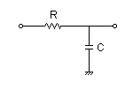
To get more bit depth, you could up the sample rate x4, and do dithering to add a rough 4 bits to the output value.  The smoothing caps would probably still work since the output rate would not have changed.  There is an interrupt associated with filling the PWM counter which would allow dithering to be added fairly accurately.  The rate can be changed by changing the prescalar value.  By default that value, which is used to divide the clock frequency, is 64.  If there was an option for 16 that would be ideal, but the next step down from 64 is 8.  If that can be made to work, it would actually provide much better performance, and more than a little improvement on noise.

The Arduino has an external clock, which overclocks the chip at 16 mhz.  When used without external clock support, the device runs at half that speed, 8 mhz, which should impact some of the assumptions here.

Analog output: Will it perform?

It makes sense that the best performance will be seen from the bare chip, which runs without the overhead of the simplified Arduino environment.  Still, without going outside of the stock configuration, there is not much difference between the two.

For quality audio? Absolutely no way.

It is clear that the Arduino and Euroduino are not going to be producing audio, at least at the sort of rates we usually associate with it – and that’s OK.  The Euroduino does not claim to generate audio (the analog out ports are marked for control voltage, just as the CV in ports are.).

For quality LFO signals? No

Control voltage signals require much less resolution than audio, although that resolution varies according to the signal type (The digital representation of modular synthesizer signals).  All types will perform well at the stock sample rates, both within the Arduino environment, and outside of it.  Where they vary is bit depth.  A LFO signal is still an audio level signal, and as such needs between 12 and 16 bits of depth.  Since the stock Arduino provides 8 bit output at best, the quality is going to be sub-par.

For envelope and volume modulation CV?  Not really.

For the monopolar, 0 to 5 volt signals that are used for volume and filter envelopes, 8 bits is just not enough.

For 1 volt per octave control signals? No.

Although the stock sample rate is probably in the range of ok, the bit depth is completely inadiquate.  Ideally the bit depth would be at least 12 bits in order to represent tuning and smooth glissandos in higher registers, and we only have 8 at most.  256 steps will not produce accurate tuning in most any octave, and will not provide a smooth transition between values.  There will be significant stair stepping (zipper noise) – just the sort of noticeable, annoying artifact that has always given digital electronic music a bad name.  It’s a pity, because that is the sort of thing I would really like to be able to produce.

Conclusion

8 bits of PWM, at 488 samples per second is not good enough.  Having said that, however the chip itself has features that can help, although using them leaves the comfortable Arduino environment behind, and that is the reason the board was selected in the first place.

Work arounds

Open Music Labs has a great add on board for the Arduino the Audio Codec Shield which adds high quality CD level ADCs and DACs to your Arduino.  There are Arduino libraries available to support this board.

audiocodec_blue-1

This works with stock Arduinos such as the Uno, as well as higher performance boards like the Leaflabs Maple (sadly discontinued).

This shield supports a sampling rate of up to 88K at a bit depth of 24  bits.  Since the Arduino can’t process samples this fast, the fact that it runs as slowly as 2K is much more interesting for our purposes.  There are two channels in and out of the board, and the board is DC coupled, which means it can output slowly changing DC control voltages without issue.  This board, an Arduino Uno, and your own signal conditioning circuitry would make a really good synth module.  It will not  not fit the Euroduino since that module is based on a much smaller device.

It is possible to dither the output to the PWM – see some of the comments above.

Digital input and output

Bit depth is 1, sample rate is well over 1K

In MIDI sequencers a temporal resolution of over 2oo times a second is considered good.  That criteria probably applies here as well.  The Arduino, Euroduino, and the raw chip are all capable of much higher rates than this.

Will it perform for the following signals?  Oh, yeah.

  • Trigger signals
  • Gate signals
  • Clock signals


Using the Arduino for electronic music #1

Introducing the Arduino and related devices

DSC07927

Disclaimer: I’m not an engineer, and some of this material approaches the speculative.  Hope it is as useful to you as it is to me, and please feel free to comment on any errors or omissions you find.

Over the last few months I’ve been studying the teensy32_front_small
features of different microprocessor families to determine which are most suited to electronic music and synthesis.  The big winner so far is the $19.00 Teensy 3.2: But that’s not what this post is about.

The Teensy 3.2 (It is, in fact pretty teensy)

This post is going to be about the Arduino, and that is for a couple of good reasons.  The Arduino is built from the ground up as an educational environment for learning about microcontrollers, and it has become, by orders of magnitude the most popular microcontroller platform for hobbyists and amateur engineers. This popularity means that it is often the first thing that comes to mind when creating a new project.

ArdGen_UNOThere is a lot to like about the Arduino:

  • The boards are inexpensive
  • Very well documented, both for hardware and for software
  • Supported by a huge community of other users
  • Supported by a huge number of libraries to do just about anything (within reason)
  • The tools needed to write and program the device are simple and free

And there are some weaknesses to the platform:

  • The device runs slowly (typically 16 MHz)
  • The device is 8 bit, which means that it is limited in the numerical processing it can do
  • The device could have more memory to store programs and data
  • The tools are best for simple, small programs and can fail when doing something complex
  • It is difficult to get high quality analog signals out of the device

In fact, the device is so popular that there is even a EuroRack synthesizer module that is built just so that you can add the device to your synthesizer rack.

The EuroDuino

DSC07926

This is Circuit Abbey’s Euroduino module.  The main board comes as an easy to assemble kit, and is supported by an extra module that will let you program the device while it is bolted into your rack.  It features:

  • Two generic knobs that can be used to change program settings
  • Two 5 volt digital inputs and outputs
  • Two 5 volt analog inputs and outputs
  • Two general  purpose switches

The processor inside the module is the Arduino Pro Mini, made by SparkFun.

This board has all the functionality of the normal Arduino Uno in a very small package which fits in the narrow Euroduino module pictured above.

The Euroduino exposes a subset of the functions that the device is capable of:

  • The 2 knobs and the two analog inputs connect to 4 of the 6 analog input pins
  • The 2 switches, the two digital ins and the two digital outs connect to 6 of the 14 digital I/O pins
  • The 2 analog outs connect to 2 more of the digital I/O pins which are set to Pulse Width Modulation (PWM) analog output.

To evaluate the practicality of the Arduino ecosystem (both hardware and software), we need to do some background research into the various signals used in Eurorack, and how much resolution they require, both in bit depth and in sample rate.  Some limitations are obvious, and some require further research, particularly when using control voltage to represent loudness and 1 volt per octave pitch.

This is discussed in these two pages:

Once you understand those things, you can evaluate how close the Arduino comes to meeting the needs of modular synthesis, which is discussed in the second part of this post:

Using the Arduino for modular synthesis #2

DSC07930.JPG

Just a reminder what it’s all about


The hurdy gurdy in Japanese game culture

1f1b_12

A fellow reader of the Hurdy Gurdy Mail list pointed this out on ebay today.  Pretty strange.  Even stranger is the fact that the game, New Rainbow Islands: Hurdy Gurdy Daibo, is around 4 years old, and no one I know in the hurdy-gurdy world has ever heard of it.  From what I can tell, (it is in Japanese after all) Bub and Bob shoot rainbows from traditional French luteback hurdy-gurdies in an attempt to defeat an evil record label.  Something that MANY of us wish we could do, actually.

Follow the ebay link for a more detailed description of the game.

I just tracked down a used copy, and can confirm that the actual game is also pretty incomprehensible.  Here is a more detailed print of the front and back art.

rainbow island


Best Hurdy Gurdy Recordings?

image_thumbA friend of mine was purchasing a selection of hurdy-gurdy music, and it got me thinking of great Hurdy Gurdy recordings.  First of all, a disclaimer: As much as I love traditional French music, the kind of hurdy-gurdy playing that really excites me are the albums where performers create something new and personal, with more relevance (presumably) to the modern communities they live in.  This might mean playing with other unusual or underused instruments (clarinet, button accordion), or playing in a band, sometimes even with electronic instruments.  Not all of those experiments can be called a success, but some of them stand the test of time.  These CDs are becoming easier and easier to find as iTunes and other services begin to take notice.  I’ll list Amazon links for the albums when available, since these are DRM free MP3s that will play on any device, and can be listened to before purchase.  As an aside, I use an online subscription service that lets me hear just about any recording on demand.

As always, your opinion may differ, so please let me know what you think in the comment section below.  Who have I left out?  For further reference Alden and Cali Hackmann (Olympic Musical Instrument) maintain an exceptionally detailed discography of Hurdy Gurdy recordings at: http://www.hurdygurdy.com/info/disc.htm and I owe it to Alden’s hurdy gurdy mail list and the folks at the yearly “Over the Water Hurdy Gurdy festival for help discovering several of the disks listed below.

Solo Performers:

These are recordings which put the Vielle A Roue (the much more euphonious French name for the hurdy gurdy) in the forground. There are two living French players who top the list: Gilles Chabenat and Patrick Bouffard. Both are excellent.

#1 Patrick Bouffard

Musiques pour vielle à roue en Auvergne et Bourbonnais

Musiques Pour Vielle A Roue en Auvergne et Bourbonnais

Fantastic playing, great arrangements, and traditional tunes make this a stand out recording and a great place to start listening.

Amazon sells DRM free MP3s of this album at the following address:

http://www.amazon.com/Musiques-pour-vielle-Auvergne-Bourbonnais/dp/B001VEOG9U/ref=sr_1_13?ie=UTF8&s=dmusic&qid=1295750830&sr=1-13

You can also listen to short snippets of the pieces without purchase.

#2  Gilles Chabenat

001

Musiques Pour Vielle A Roue “Belu Nuit”

These are original and traditional tunes.  They represent some of the finest modern arrangements for hurdy-gurdy and associated instruments (French bagpipes, violin, clarinet, etc.).  There are some vocals on the album which interrupt the flow a bit.

Amazon sells DRM free MP3s of this album at the following link:

http://www.amazon.com/Musiques-pour-vielle-roue-Bleu/dp/B0026WL2G6/ref=sr_1_6?ie=UTF8&s=dmusic&qid=1295749560&sr=1-6

Well worth checking out!

#3  Nigel Eaton (and Andy Cutting)

Panic at the Café

Hurdy gurdy and button accordion in some insanely tight arrangements.  Eaton is an award winning English player who first came to my attention from his participation in the English dance band Blowzabella (see groups below).  I love this recording – the connection between Eaton and Cutting is palpable, the playing fast and the tunes excellent.

Amazon sells DRM free MP3s of this album at the following link:

http://www.amazon.com/Panic-At-The-Cafe/dp/B002G38IJE/ref=sr_shvl_album_2?ie=UTF8&qid=1295751282&sr=301-2

Of course, you can sample the music before you buy.

#4  Gregory Jolivet

001

alt’ o solo

This is a new discovery to me, and to be honest a few months ago it would not have made it on this list.  I’ve been playing the CD a lot in the last month, and have begun to to really like it.  It’s filled with modern, complex show pieces that exercise the features of the unusual instrument that Jolivet plays, and at first I was put off by how busy it all seemed.  He is clearly a great player, (and I love what he has done with Blowzabella in recent years) but I  was put off by how chaotic and busy these tracks were.  The disk has grown on me over time and I now listen to it regularly.  I put him into the list as an example of a new performer who is still pushing the limits of the instrument.  I found no sources for the CD but did turn up a number of fine You Tube videos.  Here’s one: http://il.youtube.com/watch?v=JBI6eW5Eyt4&feature=related.image

The maker of the unusual instrument on this CD as well as the instrument in the video is Philippe Mousnier.  More information can be found on his site: Philippe Mousnier.

Another unusual instrument by Philippe Mousnier, from his online catalog.

Groups and Bands:

This is even more subjective.  There are so many cds by so many great musicians, and there is no way that I could hear them all.  But I still have opinions – don’t we all!  If I miss a good one, let me know in the comments below.

#1  Blowzabella

http://blowzabella.com/

For me (as an English speaker) it all starts with Blowzabella.  I encountered the band in 1979 in London (Several band members attended the London College of Furniture Instrument Building program in Whitechapel at the same time I did), and attended some of their dances in the basement of the Cecil Sharp house in London. The band transcends genre and ethnicity, mixing originals with traditional tunes from many sources.  Many of their original tunes have become standards in the folk community.  There is a new recording where the band gets back to their roots called Dance.  So many great hurdy gurdy players have played with Blowzabella: Starting with Juan Wijngaard, Sam Palmer, Nigel Eaton, and now Gregory Jolivet.  Distinctive features are prominently placed hurdy gurdy and bagpipes, loud wind instruments like sax, often electric bass, and button accordion.  Accordion and hurdy gurdy provide the driving rhythm for the best dance tunes, particularly in the later recordings with Nigel Eaton and Andy Cutting.

The best starting place is probably this CD:

image

Compilation

This is a collection from the earlier Blowzabella albums, and gives a good portrait of the band and it’s varied styles. The hurdy gurdy is featured prominently on many of the tracks.

Amazon sells DRM free MP3s of this album at the following link:

http://www.amazon.com/Compilation-Blowzabella/dp/B00000B0N5/ref=sr_1_2?ie=UTF8&qid=1295821685&sr=8-2

Listen and be amazed by the Blowzabella wall of sound!

#2 Malecorne

image

Malicorne IV

http://en.wikipedia.org/wiki/Malicorne_%28band%29

Malecorne falls solidly in the camp of folk rock, and hails from the decade of 1975 to 1985 that was the high point of the genre.  I’d go so far as to call it the best of any folk rock band – the instrumentation was creative and unusual, and the orchestrations and arrangements brilliant.  What puts them on this list is the use of hurdy gurdy (and bagpipes) on many of the classic tracks.  There is a compilation CD (legend) but I have not heard it, so I am just picking my personal favorite out of a field of great recordings.  I don’t think that any of these CDs will disappoint.

This CD (and many others) can be ordered from Gabriel’s web shop:

http://www.gabrielyacoub.com/boutique/index.php

and downloads can be purchased at:

http://www.leroseau.net/catalogue/liste-des-produits.html

In fact, I see some odds and ends that I ‘m going to download as soon as I’m done writing this post!

#3  Hurdy-Gurdy

image

Nordic roots and very modern, almost techno arrangements of original and traditional tunes.  The band promotes the instrument as a “medieval synthesizer”, generating percussive effects and odd sounds.  This CD contains recordings that have been cut up and re-arranged into the pieces you hear.  “Our world of wood, gut strings, cranks and laptops might seem pretty small, but we are proud of it” says Stefan Brisland-Ferner.

The CD is available used from Amazon associates.  Unfortunately no samples are available on line, and the record label NorthSide is not promoting it.

The Tiny Tim Effect

image


In Jim Beloff’s book, The Ukulele, A Visual History, there is a table that contains the yearly number of ukuleles produced by the Martin Guitar Company.  It provides an interesting glimpse into a half century of (mostly) American popular musical history, and of course provides a view into the popularity of the instrument.

clip_image004

The major high and low points of the last century are represented – The great depression and World War II both have a significant impact on the popularity of the instrument.  Cultural milestones appear as well – the growing American fascination with Hawaii and the flapper era coincide to create the first boom in uke sales.  The second big boom coincides with Arthur Godfrey’s rise and his popularization of the instrument.  This boom lasts fifteen years.

The popularity of rock and roll and a backlash against the uke fad drive numbers down in the 60’s, but the instrument still seems to do fairly well until 1968, when just before the end of the graph, something amazing happens.  Production numbers crash to double digits, a place where they have never been (other than the first year of production).  What happened?

A lot happened in 1968 – but only one story includes the uke as a major player. This story:

 
Tiny Tim on Laugh In


This was the year that Tiny Tim hit the national stage.  He recorded an album for Reprise, and Rowan and Martin’s Laugh-In introduced him to America.  Although the album reached the #5 spot in the charts, for once fame did not translate into ukulele sales.  What Jack Benny failed to do for the violin, Tiny Tim did for the uke.  His second appearance is really what he is remembered for.

I’m a huge Tiny Tim fan, but even I did not rush out in to purchase an instrument in 1968.  After that performance, the uke went into a death spiral outside of Hawaii where it was too much a part of culture to fade away. 

People as influential as George Harrison continued to play and popularize the uke, it is only in the last 10 years that the instrument has seen a renaissance, and now, only after a slow, steady recovery are there great players popularizing the instrument again.

I’ll leave you with a couple of favorite uke videos:

What do you think of the uke?  This post? Tiny Tim? Leave your comments below.

The Hurdy Gurdy


I’ve been wrestling with the challenge of introducing the hurdy-gurdy to blog readers. I’ve lived with and around the instrument for most of my adult life, and simply don’t know where to start.

I first saw the instrument in 1972 in the collection of a music store just outside of Washington DC.  It looked much like the guitar shaped instrument pictured below.  The store owner was happy to take it to a back room and let me examine it – at the time there was little written about the instrument and even less recorded, and it took research in the Library of Congress to get an idea of what the instrument was and how it was played.

A while after that (1989) I traveled to London to study instrument building in the Early Woodwind program at the London College of Furniture.  I met Sam Palmer, who was a maker and player of the instrument and a student in the stringed instrument division of the school.  Through his associates in the band Blowzabella and through my friend Mac McCreary, I was introduced to the contemporary folk music associated with the instrument.

Here’s the deal: while most Americans have never heard of the instrument, It has been among the most popular instruments of the last 1000 years. Europeans get this – they don’t think that history started in 1776, and they have the advantage of being surrounded by surviving instruments and folk traditions that reflect this long history.

Organ_grinder_with_monkey

This is not a Hurdy Gurdy

This is a great picture of an organ grinder, monkey, and barrel organ.  Not a Hurdy-Gurdy.  Although confused in the last century, particularly in popular culture, the two instruments have nothing to do with each other.  Not even the monkey.

Another confusing reference is Donovan’s song, Hurdy Gurdy Man.  The song is vague and does not really describe any existing instrument, but on the other hand, it’s a great song.

So, what IS a Hurdy Gurdy?

The hurdy gurdy that most people play today is a style that became popular in the late 17th and early 18th centuries, and was manufactured traditionally in France until the early 1900s.  It experienced a revival in the 1970s, along with many other folk traditions, and is now built by several excellent makers in Europe and the US.

It is a stringed musical instrument, played using the keys that you can see in the first illustration above. These keys touch the melody strings (instead of your finger-tips) which allows you to play melodies.

louvet_drehleier

  • It is a drone instrument.  This means that in addition to the melody strings, there are drone strings that (not surprisingly) produce a drone to back up the melody.
  • The strings are not plucked or bowed, but made to sound by rubbing against a wheel that is treated with rosin, much like a bow.  This produces a constant sound, much like a quieter version of a bagpipe, where the drones and the melody strings sound all the time.
  • Perhaps the most distinctive part of the hurdy gurdy is a “buzzing bridge”.  One of the drone strings goes over a specially shaped bridge that buzzes when the wheel is sped up slightly. this allows the player to create a complex percussive accompaniment to the tune being played, and is one of the features that makes modern hurdy gurdy music so compelling.

To get a better idea of what the instrument can do, listen to it’s master players.

YouTube has some amazing performances, like Gregory Jolivet above .  A more traditional example of hurdy gurdy playing can be found on the album Musiques pour vielle à roue en Auvergne et Bourbonnais by Patrick Bouffard.  Follow the link to hear clips of the album on Amazon – all of the tracks are exceptional so start at the top and work your way down.

I’ll list some more of my favorites in a future post.  After you listen, add a comment and let me know what you think –  Like it? hate it?  If you have a favorite, be sure to add it in the comments below.


I stood on a Star Trek transporter and nothing happened

Back in the 60’s my uncle Jerry was a science fiction writer. He had some fame in the 50s as a novelist, and became involved in the motion picture industry. I suspect his career was unfairly stunted by his involvement with HP Lovecraft’s gothic horror novel “The Color out of Space” for Shepperton Studios. The film was released in the US as “Die Monster, Die”, Die,_Monster,_Die!and features the last performance of Boris Karloff. It is also rumored to contain massive amounts of acting under the influence of LSD. As such, it resembles Hertzog’s “Heart of Glass” as much as it does a HP Lovecraft story – not well received at the time, but increasingly well regarded as a cult classic in modern times (rotten tomatos, 71% and rising).

In any case, he was a friend of Gene Roddenberry, and was one of the first science fiction authors tapped to write screenplays for a concept that had just been greenlighted called Star Trek. His first contribution to the canon was “The Corbomite Maneuver”, which was the first (non-pilot) episode filmed, although it was shown out of order (#3) when the series launched. The episode is famed for other reasons as well – the first appearance of Clint Howard (Rons brother, the member of the family everyone thought was going places) as a child actor playing the role of Balok, captain of the mighty Fesarius.

What this meant for me was that when my family visited Uncle Jerry in the spring of 1966, he arranged for us to tour the set, and watch the filming of an episode. We had no idea what the show would become, really we had no idea what it was even about since it had not been broadcast yet. Still, as a science fiction fan, I was excited to see the inside of a real tv show – and a science fiction one at that. We were not allowed to take pictures – in retrospect a great shame, but understandable at the time.

Mudd’s Women was being filmed the day we visited, (the second episode filmed) and we saw one scene being filmed – where a miner of lithium crystals (not yet dilithium) and one of the women have a fight – I remember a line about “Women’s cooking”.
We were introduced to William Shatner, and Leonard Nimoy, who were in costume and waiting for their scene. Both were polite, with Shatner distracted by a conversation about his motorcycle. Nimoy complained to Jerry about his ears not fitting. We shook hands and moved on.

We toured the set, and I was struck by the setcraft – boulders made of paper mache and tin foil, covered with spray texturing. There were several sections, each containing sets. In one we walked up a wooden ramp to the side of a large structure walled in surplus cardboard boxes, and walked through a door onto the bridge of the Enterprise. I was struck by the difference between the outside and the inside – with nothing better to compare it too, the control panels and tiered bridge were impressive, even with the inexpensive materials and repurposed elements. We looked around freely, and I sat in the captain’s chair (this probably made Jerry nervous, but no one was around to see). We then toured other sets – the transporter room stays in my memory. We stood on the transporters, but of course had no idea how they would be used in the show.

That captain’s chair is now on display in Paul Allen’s science fiction museum, housed in a building by Frank Gehry. My cousin Ed and I visited it not too long ago. Ed had been with us on the tour that year and so it was a homecoming for us both. I’m told that Paul has never actually sat in the chair – it is a museum artifact now, so I’ve done something that one of the richest men in the world can’t do. (or is at least smart enough not to do).

In the late 90s I came across a Star Trek action figure of Balok, which I sent to Jerry along with a comment on how Jerry had obtained pop culture immortality. I’m told he kept it displayed in his office till he passed in 2002.

Euphonia is back

The previous blog by this name was perhaps better looking, but not well funded.  This means that it died due to neglect and due to changing priorities and interests.  It is now back, with some of the better articles reprised, some new material added, and a new focus on electronic music, modular synthesis, and general instrument making.  I think.