Testing the analog output resolution of the Euroduino:
Note: Audio samples are not included yet, and there are more tests to be done on the sample rate section.
The previous articles in this series are:
So far, we have dealt with the subject in the abstract, using best case scenarios and working from specification sheets. Reality is, as always much more messy. To start with, lets look at the most problematic part of the platform, the analog outputs of the Arduino in it’s default state using the Euroduino module as a testing ground.
It is simple enough to write an Arduino program to output very specific values, and to chart those values to see if they are being translated as we expect them to be.
Bit depth
Ideally, bit depth should be at least 12 bits. The PWM output of the Arduino falls considerably short of that, with only 8 bits of resolution. Lets see how that 8 bits performs.

This chart compares the values used in analogWrite() commands with the specific voltages output on the cv out 1 port. The code to do this is simple, and I stepped through the values in units of 12 so that I could get good voltage readings and not spend all day comparing values in the serial window to my voltmeter.
What it shows is that the Euroduino/Arduino has good linearity, so we can make some observations that will make programming easier:
- Output changes linearly compared to input.
- There is a inverse relationship between the written bit value and the voltage.
- The circuitry of the Euroduino over and undershoots the 0 to 5 volt range that is common for modular control signals. 0 volts starts at around 246, and 5 volts ends at 12. This means that (for the tested device at least), the range of 0 to 5 volts falls into the output range of 12 to 246, giving a 5 volt range (and therefore 5 octaves) spread over 234 values.
- An octave then is represented by 46.8 steps (234/5=46.8). Even though the analogWrite() command can only take integer values, it is valuable to track these values as floating point values so that errors do not accumulate.
- A semitone is represented by 3.9 steps. (234/(12*5)=3.9).
Hearing is believing
It is simple to write a program to play a slow descending glissando in order to see how smoothly the device can perform. We already know from part two of this series that the output is not expected to be smooth, rather that there will be some noticeable stair-stepping, and that note values are not going to be precisely in tune. A simple program can tell us if this is actually the case.
All the code in this post will use some common definitions, taken from Tim Ressel’s sample program that accompanies the Euroduino.
// These constants won't change.  They're used to give names
// to the pins used:
const int analogIn1Pin = A0;  // Analog Input 1
const int analogIn2Pin = A1; // Analog Input 2
const int analogPot1Pin = A2;  // Pot 1
const int analogPot2Pin = A3; // Pot 2
const int analogOut1Pin = 5;  // Analog Output 1
const int analogOut2Pin = 6; // Analog Output 2
const int DigitalIn1Pin = 8;  // Digital Input 1
const int DigitalIn2Pin = 9;  // Digital Input 2
const int DigitalOut1Pin = 3;  // Digital Output 1
const int DigitalOut2Pin = 4;  // Digital Output 2
const int Switch1Up = A4;  // Switch 1 Up
const int Switch1Dwn = A5;  // Switch 1 Dwn
const int Switch2Up = 7;  // Switch 2 Up
const int Switch2Dwn = 2;  // Switch 2 Dwn
void setup()
{
    /* Set up I/O pins */
    pinMode(DigitalIn1Pin, INPUT);
    pinMode(DigitalIn2Pin, INPUT);
    pinMode(DigitalOut1Pin, OUTPUT);
    pinMode(DigitalOut2Pin, OUTPUT);
    pinMode(Switch1Up, INPUT_PULLUP);
    pinMode(Switch1Dwn, INPUT_PULLUP);
    pinMode(Switch2Up, INPUT_PULLUP);
    pinMode(Switch2Dwn, INPUT_PULLUP);
    Serial.begin(9600);  // if needed by Serial.print() etc.
}
To output a descending glissando, add the following code:
unsigned char Out1 = 12;
void loop ()
{
    analogWrite(analogOut1Pin, Out1);
    Out1++;
    if (Out1 > 246) Out1 = 12;
    delay(500);
}
Here is a sound file created by routing the CV 1 output of the Eurduino (running this program) to a Tiptop Z3000 oscillator.
Stair-stepping is obvious – the pitch descends in a series of discrete steps, not smoothly. Looking at the code, it is clear that this is pretty much the maximum resolution achievable without hacks.
Sampling rate
PWM on the Euroduino runs at a particular frequency determined by the system clock speed. For timer 0, which is what the Euroduino exposes, the PWM frequency is determined by the system clock divided by the prescaler, and then by the 256 steps used by the counter. 16 Mhz / 64 / 256 = 976.56 Hz, roughly a sample rate of 1k. It is possible to increase this rate, but not without causing other Arduino functions to malfunction.
You can call analogWrite() much faster than 1k of course, but it is wasted effort and will likely cause unpredictable results since the compare value would be changing unpredictably.
Just for fun you can test this and remove the delays and print statements from the last program to see how fast a stock Arduino program can call analogWrite(). (print always adds a lot of overhead that would otherwise mess up calculations).
unsigned char Out1 = 12;
unsigned long startMicros;
unsigned long stopMicros;
unsigned char Out1 = 12;
unsigned long startMicros;
unsigned long stopMicros;
void loop ()
{
    //start test now
    startMicros = micros();
    for (unsigned int x = 0; x < 1000;x++)
    {
        // write a descending sawtooth wave to the output
        analogWrite(analogOut1Pin, Out1);
        Out1++;
        if (Out1 > 246)Out1 = 12;
    }
    // print takes place outside of the test loop
    stopMicros = micros();
    unsigned long resultMicros = stopMicros - startMicros;
    float samplesPerSecond = (float)1000000000 / resultMicros ;
    Serial.print ("Samples per second = ");
    Serial.println (samplesPerSecond);
    delay(5000);  //long enough to read the output
    //repeat and see if there is variance in the output
}
Here is the output of the test:
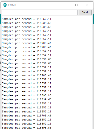
(why the Arduino does not allow copy is beyond me)
This tells us that we can write the output roughly 118 times faster than the output is updated. Adding the second output port:
analogWrite(analogOut2Pin, Out1);
brings us down to around 62 times faster.

In either case, this sounds plenty strange.
It would be nice to know when it is time for a new sample to be written, and there are interrupts intended to allow this sort of thing.
There is an interrupt that tells us when the counter has overflowed and reset, which would be perfect, but that is already taken by the Arduino library.
The next best thing is to use an interrupt that triggers when the counter reaches a certain number. Adafruit, one of the primary distributors for all things Arduino, has a good info page at: https://learn.adafruit.com/multi-tasking-the-arduino-part-2/timers which gives detail on strategies for using timer0 interrupts within the Arduino environment.
The following code sets it to trigger at the maximum value of the counter, which is about as close to the overflow interrupt as we can get.
This code is added to the setup loop:
OCR0A = 0xFF;
TIMSK0 |= _BV(OCIE0A);
And here is the code for the interrupt body itself.
unsigned int count = 0;
bool state = 0;
// Interrupt is called once a millisecond, every time the PWM counter maxes out.
SIGNAL(TIMER0_COMPA_vect)
{
    count++;
    if (count > 1000)
    {
       count = 0;
       if (state == 0) state = 1;
       else state = 0;
       digitalWrite(ledPin, state);
    }
}
Add this code to an Arduino program, and the interrupt will be called one thousand times a second. In this example, it simply flashes the led on pin 13 on and off, telling us that it is working.
Next, we should update our descending tone code to call analogWrite() only when it is safe. I also added a delay of half a second so that the steps of the glissando would be more apparent.
unsigned int count = 0;
unsigned char outputValue = 12;
// Interrupt is called once a millisecond, every time the PWM counter maxes out.
SIGNAL(TIMER0_COMPA_vect)
{
    count++;
    if (count > 500) //change every half second
    {
        count = 0;
        outputValue ++;
        if (outputValue > 246) outputValue = 12;
    }
    analogWrite (analogOut1Pin,outputValue);
}
void loop ()
{
     // all other code goes here and will not interfere with the updating of the output values.
}
Note that there is no code left in loop – all management of the output buffer is done in the interrupt!
Hacks to improve output bit depth
It may be possible to dither the output to add a couple of bits resolution. Dithering is, roughly speaking when you alternate two adjacent values in an attempt to simulate a third value that lies between them. What this would take would be to change the value used in analogWrite() every time a sample is output to add either a 1 or a 0 to the output depending on output value. This would allow an extra bit of precision at the cost of some ripple in the output, and some complexity to the program. With any luck, the filter capacitors on the output of the Euroduino (that are needed for PWM anyway) will help remove most of this additional ripple.
Here’s a short experiment to see if dithering makes any difference, and if so, if it has any artifacts that are unwanted:
unsigned int outputValueA = 12;
unsigned int outputValueB = 12;

bool count = 0;
// Interrupt is called once a millisecond, every time the PWM counter maxes out.
SIGNAL(TIMER0_COMPA_vect)
{
   // toggle between dithered values
   count = !count;
   if (count) analogWrite (analogOut1Pin,outputValueA);
   else analogWrite (analogOut1Pin,outputValueB);
}

unsigned int increment = 24;
void loop ()
{
   // without dithering
   Serial.println ("without dithering");
   for (increment = 24; increment < 300; increment ++)
   {
     delay (250); // change values every 1/2 second.
     if(increment % 2) // if increment is odd
   {
     // don't dither output
     outputValueA = increment/2;
     outputValueA = (increment/2);
     digitalWrite (ledPin, 0);
   }
   else //increment is even
   {
     // don't dither output
     outputValueA = increment/2;
     outputValueA = increment/2;
     digitalWrite (ledPin, 1);
   }
 }

 // with dithering

 Serial.println ("with dithering");
 for (increment = 24; increment < 300; increment ++)
 {
   delay (250); // change values every 1/2 second.
   if(increment % 2) // if increment is odd
   {
     // dither output
     outputValueA = increment/2;
     outputValueA = (increment/2)+1;
     digitalWrite (ledPin, 0);
   }
   else //increment is even
   {
     // don't dither output
     outputValueA = increment/2;
     outputValueA = increment/2;
     digitalWrite (ledPin, 1);
   }
 }
}
As it turns out, that works well, even if it does cut the actual update rate by 50 percent.
Dealing with PWM and dithering noise
When I attached an oscilloscope to the output channels of the Euroduino, I expected to see some noise from the dithering code above, but expected the output to otherwise be fairly clean. I was surprised to see how much ripple was making it out of the PWM, and how much effect this had on the quality of the audio from the voltage controlled oscillator (VCO). I was also surprised to see what little effect the dithering was having on the output.
I consulted the online RC Low-pass Filter Design Tool to get some values for an additional low pass filter, this time set to a conservative 1K (remember that 1 K is about the lowest we can safely go when dealing with control voltages).
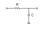
The returned values were:
1uf for the capacitor
160 ohms for the resistor
For 2k, the program suggests 820 ohms and a 0.1uf capacitor. For 500 hz cutoff, the values are 1uf and 330 ohms.
Implementing the 1k circuit on a breadboard and adding it to the outputs of the Eruoduino, the ripple goes away. In addition the audio from the VCO sounds cleaner – previously there were what sounded like faint difference tones in addition to the actual sine wave of the audio – perhaps an unintentional bit of FM synthesis. These have disappeared completely.
Modding the circuit is cheating, I suppose, but it, along with the dithering of the output has produced a much more musical result. I suppose that if you have need for DC control voltage response above 500k, this might not be for you. And if you do, let me know – I’m really curious to know what it might be and add it into my considerations.


